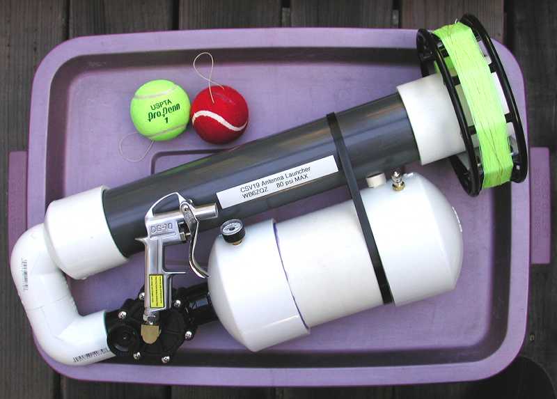
CSV19 Pneumatic Antenna Launcher Instructions
Document Notes

Version 2.10  5/4/2008
The builder wishing to do it yourself will find instructions below on doing that. If you have purchased a kit you can skip over the detailed procurement and preparation instructions to the Kit Assembly instructions below.
The CSV17 Launcher differs slightly from the CSV19 model. The overall length is reduced to 17 inches, so the barrel and chamber are shorter. The chamber is also constructed from 3" pipe instead of 4" pipe, so the chamber endcaps are also 3". This reduces the weight and bulk considerably. It does require slightly higher pressures to operate, but the smaller volume pumps up very quickly. The CSV17 is well suited to 12 gram CO2 cartridge usage. The maximum height reached by the CSV17 is over 150 feet, whereas the CSV19 can reach 200 feet under good conditions.
The two bored endcaps are the most difficult parts to make for this launcher. Drilling and tapping the valve is a bit difficult as well, and requires a different size drill and tap than the pressure chamber drilled and tapped holes.
The quality of your work affects the safety of the finished launcher. Just the other day I read about someone who completely forgot to glue one of their joints in the pressure section of their launcher (a design of their own, not this one). The parts were wedged together very tightly (this can happen while trial fitting - be careful). It held for awhile, then let go with a bang at high pressure. The PVC part that came off turned into a projectile and bounced around their shop and broke the overhead lights, sending a shower of broken glass down on the builder. These joints, done properly, have a significant safety margin. Do them well.
Krylon makes paint specifically for plastic called Krylon Fusion. It works well on PVC.
The pipe we are using is not necessarily 'pretty' when it is purchased - it may have scratches, rust stains, etc from the storage and transportation. Make sure the material is sound - not cracked or fractured or deeply scarred with scratches. Occasionally I have to throw some away due to these flaws, especially in the larger diameters and near the ends. The pipe looks a lot better after scrubbing with a fine steel wool type pot scrubbing pad.
It is important to avoid cracking or fracturing the PVC when working with it. Use sharp tools and avoid cutting too fast. Even minor fractures can lead to failure later on. This can be a problem when drilling, tapping, boring, or cutting the PVC. Any fractured PVC should be recut to remove fractured parts or discarded.
| Clearly familiarize yourself with all parts before proceeding. Trial fit them loosely together to insure that they are all accounted for and the fit is snug. Be careful in trial fitting them as they can stick together if inserted too far. Do not insert them with any force - stop when slight resistance is felt. It is normal for them to fit tightly - the cement lubricates the joints during assembly so they can be fully inserted. Y | |
| Wash the PVC pipes and tubes. This includes the barrel pipe, pressure chamber pipe and the three joiner pipes for the launcher. Use a steel wool type pot scrubber to get them clean. Washing the other PVC parts is optional, and avoid the steel wool potscrubber on the shiny finish of the fittings, as it may scratch and dull them. Use soap and water with a washcloth to clean the fittings. Dry the PVC before glueing. | |
| OPTIONAL - Paint the barrel with Krylon fusion spray paint. Mask off 1-3/4" at one end to keep it clean of paint for cementing to the launcher. We use Safety Blue. The Pressure Chamber may also be painted, mask off both ends and keep them paint free about 1-3/4" for cementing. | |
| Solvent cement the ramrod handle (1/2" pipe) into the ramrod bushing (1/2 by 1.5 or 2"). Insure that the pipe is fully into the socket. Note that these parts often fit together so tightly without cement that cementing may be optional, but this is a good part to practice on. NOTE that wherever the instructions say "solvent cement" you should use PVC primer and PVC cement. EPOXY will be specified for the few joints it is to be used. | |
| Locate the 1.25" elbow that has been fitted to the bored hole in the 2.5" endcap. Observe that the elbow has one end that fits better into the barrel endcap than the other due to the raised lettering that interferes with the tight hole in the endcap. Reserve the better fitting end for the barrel endcap - mark it. | |
| Solvent cement the 1.25" short joiner pipe into the other end of this barrel elbow. (Note that the 1.25" is the pipe size, the actual size is closer to 1.5" in diameter - these are pipe sizes.) Prime the interior socket of the elbow with purple primer, and half the 1.25" short joining pipe. Coat the socket and half the pipe with a coat of PVC cement. Stand the 1.25" pipe with the cemented end up on the work surface. Push the elbow down onto the pipe until it is fully seated. Clean off the excess glue and set aside to dry. | |
| Solvent cement the 1" to 1.25" bushing into one end of the other 1.25" elbow. One end of the elbow has two mold lines. Cement the bushing into the end that does not have mold lines (as these lines aid in alignment of the elbow during a later step). If the bushing has been shortened it will fit approximately flush, otherwise it will stick out a bit. MAKE SURE that the bushing is installed the right way. The stop ring should not interfere with the later installation of the 1" pipe inside to a depth of 3/4". NOTE that wherever the instructions say "solvent cement" you should use PVC primer and PVC cement. Prime both the pipe and the socket with purple primer, then coat both surfaces with a thin layer of cement. Set the bushing with the internal stop ring up on a paper towel on the work surface. Push the elbow fully down on the bushing. Push against a paper towel on the benchtop to seat the bushing fully in. Wipe up excess cement with paper towels and Q tips. | |
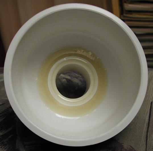
| Solvent cement the 1" diameter short pipe and ring into the bored hole in the large pressure chamber endcap. NOTE - after 9/15/05 this short pipe is supplied using the stronger schedule 80 material. It is dark grey rather than the usual white PVC. It is installed using the same procedure and cement as before. (Depending on your parts it might be a slightly different length. It should fill the coupler ring, the endcap and have enough left sticking out to fully fill the valve socket - 3/4". See the cut schedule above for details). This joint holds full pressure for extended periods so it is imortant that it be a good joint. Prepare the endcap, masking it on the inside to protect the inside vertical glueing surfaces to be used later for the pressure chamber pipe. Position the 1" pipe so it extends into the endcap about 1/3 of an inch. There should be 0.75" of the pipe sticking out of the endcap to fit the socket in the sprinkler valve. (This may need to be adjusted depending on your particular sprinkler valve socket depth). Wrap masking tape around the 1" pipe where it extends from the endcap to mark where it should sit and discourage cement leakage there. The joint should be tight enough that the cement will not leak. Test the ring on the pipe inside the endcap. Clear any burrs that interfere with installing the reinforcing ring over the 1" pipe. Remove the ring and set it aside. Remove the pipe from the endcap. Using a Q-tip type cotton swab on a stick applicator to apply purple primer to the inside of the hole bored in the endcap, and to the inside of the reinforcing ring. Apply purple primer to the pipe end that is not masked. Apply cement to the hole in the endcap, and to the pipe. Slide the pipe into the endcap up to the masking tape. Apply cement to the inside of the coupler ring and slide that onto the end of the pipe inside the endcap until it contacts the inside of the endcap. After a minute or two remove the masking tape from the 1" pipe and clean up the excess cement. | |
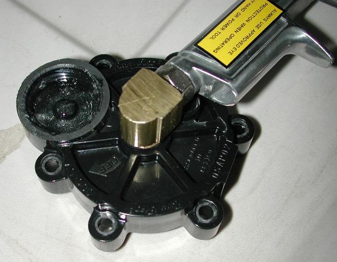
| Disassemble the Main Valve by removing the six screws that hold the valve top to the valve body. Remove and set aside the rubber diaphragm and spring and screws. Note how the diaphragm and top are aligned for later re-assembly. | |
| Epoxy the three small holes in the valve top. One is the manual actuation port. The other two small holes are the solenoid input and output ports. The inlet port is a small hole in the bottom corner of the solenoid socket. The outlet port is in the center of the solenoid socket. Clean the areas with alcohol. For proper epoxy adhesion these areas must be clean. Mask the inside/bottom of the cap to prevent epoxy from going beyond the three holes toward the inside of the valve. Blue masking tape is good for this, it does not leave adhesive residue. Carefully dribble epoxy down into the small threaded hole (the manual actuation hole). Apply epoxy into the larger threaded solenoid socket and insure that both small holes in it are plugged by the epoxy. This can be done with one large puddle or two small ones. | |
| Solvent cement the other 1" dia short pipe to the outlet of the sprinkler valve. This is the pipe that will go into the 1.25:1 bushing. (Depending on your parts it may have a slightly different length. The length should be enough to just fill the sprinkler valve and the bushing). Hold and clamp it tightly - the sockets on the sprinkler valves are tapered and the pipe can creep out if not held in tightly for a few minutes. | |
| Solvent cement the solid pressure chamber endcap on the end of the pressure chamber pipe. Always use purple primer on solvent cemented PVC joints. Get a good coat of primer on both joint surfaces - inside the socket and outside the pipe. This is a large joint, use plenty of cement. Large joints can leak or stick before fully seated if insufficient cement is used. Get it all the way out to the edge to avoid a leak when the holes are drilled and tapped into the plastic later. | |
| Take a Glue Drying Break. The durations of these breaks are dependent on the cement that is being waited on, and the stress of the next step. Solvent joints can be handled fairly soon, epoxy really depends on the particular cement. Follow manufacturers recommendations. In general, 8 to 24 hours should be sufficient. An easy way to do this is to stop at the glue breaks for the day and start fresh the next day. | |
| [ OPTIONAL - it is no longer required to use epoxy in the endcaps. ] Make a mask to protect the inside of the pressure chamber endcap from epoxy using four 3 by 5 inch cards. Lay them out in a line, overlapping them by about one inch. They should cover an area about 3.5 inches by 15 inches. Tape them into this arrangement. Alternately, a piece of heavy paper or thin cardboard may be cut to 3" by 15". | |
| [ OPTIONAL - it is no longer required to use epoxy in the endcaps. ] Epoxy support the pressure chamber exit pipe. Support the endcap so that it is level. Wrap the cardboard mask into a ring and position it inside the endcap against the inside cement surface to protect it from epoxy splash. Mix a batch of epoxy thoroughly and pour a puddle of epoxy around the 1" pipe inside the endcap. Approximately 20 mL, or half of a 2 ounce epoxy kit (a kit of two 1 oz tubes of 1:1 epoxy and hardener) should be enough. The epoxy puddle should support the pipe/coupler ring to a depth of approximately 0.2". Allow to set overnight, insuring that it stays in the proper orientation with the pipe, keeping the endcap level. Use a level to insure that it is actually level before leaving it to cure. | |
| Install the trigger valve to the street elbow using teflon tape. Starting in late 2007 the trigger valves supplied are female threaded and this requires a short threaded adapter pipe. IMPORTANT - Remove the tip, if any, from the air duster and discard it. Good airflow is requires for proper launcher operation. Thread the air duster into the brass elbow. Use the double male adapter tube if required. Position the street elbow such that, with the outlet tip of the air dister pointed away from you the brass elbow male threads point to the left. The threads should be tight. The flat side of the brass elbow should be parallel to the flat of the handle. The solenoid attachment hole that you filled earlier sits toward the rear of the launcher. The solenoid socket is toward you and the valve top oriented so the valve would be to the left. The male streen 90 threads then screw into the valve top center about 3 to 4 turns. The trigger should sit over the small threaded hole (the manual actuator hole) and between two mounting screw holes. Place the two screws into the holes before positioning and insure that the screwdriver access past the blowgun handle is ok. On the inside of the valve top the street elbow should even with or just barely enter the valve. The brass should be above the flat level of the interior of the valve where the diaphragm moves by about 1/8".. It should not protrude into the valve and limit the diaphragm motion. | |
| Solvent cement the second 90 degree elbow to the other end of the short 1.25" diameter pipe that is already cemented to the other elbow. Insure that it is fully together and flat and the open ends of the elbows are pointed the same direction. This forms the U assembly. | |
| Solvent cement the pressure chamber pipe with cap into the other endcap (with the outlet pipe). This is another big joint - use plenty of cement. | |
| Take a Glue Drying Break | |
| Solvent Cement the U assembly into the 2.5" barrel endcap. Using masking tape, cover the inside of the endcap where the barrel will be glued later to prevent cement from spreading there. Use PVC primer and cement. You can apply the primer with a Q tip to prevent it getting where you don't want it. Then apply PVC cement to both the inside of the bored hole and the outside of the elbow. Position the endcap as far as it will go onto the elbow without forcing it. If forced too far it will not be concentric with the elbow. | |
| Take a Glue Drying Break | |
| [ NOTE - this epoxy is optional. ] Prop the elbow and endcap level to make the epoxy flow properly. This is a good joint to use the flow-mix epoxy on, if you have any. I have used a whole 14ml flowmix kit for this joint. The long nozzle gets it down into the joint easily. Or, mix a batch of epoxy and carefully pour it into the endcap around the elbow. Insure that it remains supported and undisturbed while the epoxy cures, and that the proper angle is maintained. | |
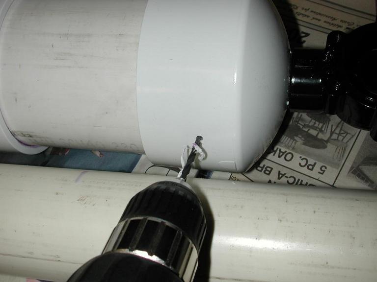
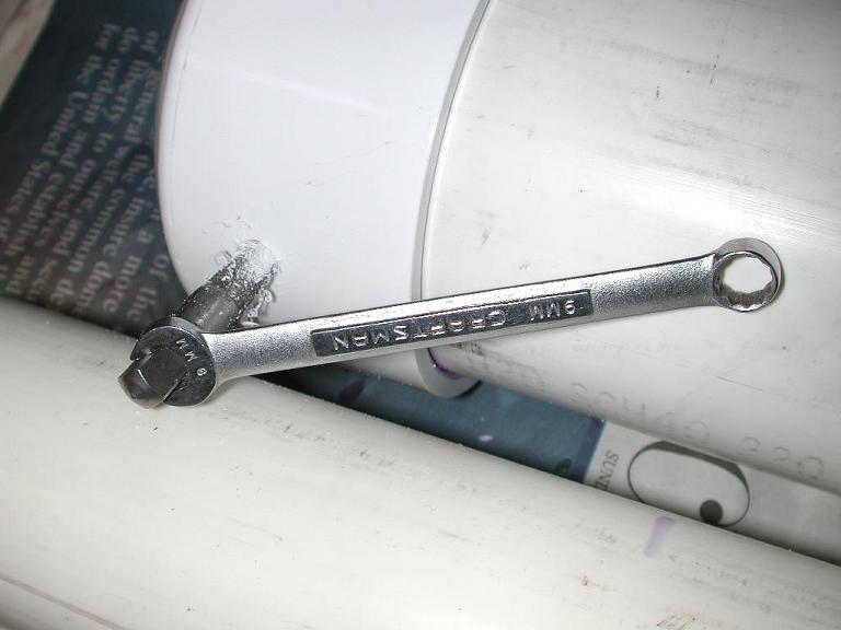
| Drill and tap the two holes into the pressure chamber 1/8-27 NPT. [ NOTE - if installing a pressure relief valve there will be three 1/8 NPT holes to drill and tap. ] Locate them along a straight line parallel to the axis of the chamber, close to the barrel. Each hole should be about 1.5" from the 'edge' of the endcap. Drill a 1/8" hole first, then enlarge with a 5/16 drill. The tap recommends a larger drill but in plastic I prefer a slightly smaller hole and allow the tap to finish the hole. The most difficult part of the drilling/tapping is getting the hole perpendicular to the surface. Take some care to do so, and keep the tap straight into the hole so the gauge and schrader valve come out straight when installed. Tap without lubrication, but work the tap back and forth as you go forward to cut the PVC. The tap is tapered - the deeper you run it in, the larger the hole and threads. Approximately 1/2 to 2/3 of the tap cutting threads has worked well for me - this makes the threads fairly tight for a good seal. | |
| Clean out the PVC dust - use plenty of compressed air or rinse repeatedly with water. This dust may interfere with valve sealing if not completely removed. (If the launcher leaks from PVC dust, just disassemble and clean the valve). | |
| Take a Glue Drying Break | |
| Solvent cement the valve outlet tube into the bushing of the barrel assembly. Align the barrel assembly with the valve quickly before the glue sets. The valve top should be parallel to the elbows, the trigger handle should sit alongside the barrel. You may wish to temporarily install the valve top and trigger assembly to aid in alignment. Refer to the photos. Clamp or hold in position until set. | |
| Take a Glue Drying Break | |
| Solvent Cement the pressure chamber assembly to the valve inlet. If it is wet from cleaning out the dust, allow it to dry first. This is a critical joint, be sure to clean, purple prime, solvent cement and clamp it well. This is a tight tapered joint, clamp it tightly to avoid creep. Observe the alignment of the holes for the gauge and schrader valve slightly to the right of the barrel when viewed from behind. Make sure there is enough clearance for the gauge and access to the schrader valve for filling. Refer to the photographs for additional guidance. | |
| Take a Glue Drying Break | |
| OPTIONAL - if you have a pressure relief valve (they are included in some kits, and are available as an optional item on the order form), drill and tap a third hole opposite the gauge hole on the 'back' side of the barrel, about 1.5 inches from the edge of the endcap. Trial fit the barrel to help find the position for this hole. Placing the pressure relief valve close to the barrel will allow the launcher to lie on a flat surface without touching the relief valve. Install the pressure relief valve in this hole. | |
| Install the schrader valve and gauge on the pressure chamber. Locate the pressure gauge toward the rear next to the trigger valve, and the schrader valve toward the front of the Launcher. | |
| Solvent cement the barrel into the 2.5" endcap. | |
| NOTE - DO NOT GLUE THE REEL TO THE BARREL. The reel is a friction fit for portability and ease of use. | |
| Take a 24 Hour Glue Drying Break!!!!!!!!!!!! | |
| Install the valve top/trigger assembly. Align the top of the sprinkler valve with the body by lining up the hole under the solenoid socket (now epoxy filled) with the hole in the diaphragm gasket and valve seat next to the valve outlet port. When starting each screw, turn it slowly backward until it 'clicks' into the thread previously cut, then turn gently forward and slide into the existing thread cut. The screw should go in easily and not start cutting new threads. Carefully tighten the screws in rotation. Do not over-tighten. Observe the compresssion of the rubber diaphragm gasket at the edge of the valve top as the screws are tightened in rotation. The rubber gasked should just show stress at the edges where the plastic is compressing it when adequate tension is reached. A power screwdriver is NOT recommended for this task - the feel of a manual screwdriver is preferred. | |
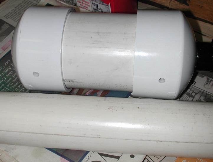
| New CSV19 Super kits are supplied with a Cable Tie and a barrel
to chamber spacer. Tieing the barrel to the chamber increases the strength of the system
which can reduce breakage if the launcher is dropped on a hard surface.
The supplied spacer is a short length of 1/2" PVC square rod
with double stick
foam tape on the ends. This is the right spacing for most launchers, but some will require
a different length spacer. Cut a new spacer from a length of dowel or other suitable
material if needed.
Remove the cover from the foam tape and insert the
spacer between the barrel and chamber.
Stick it to the chamber and barrel.
Wrap the large cable tie around the barrel and chamber and tighten with the joint
on the back side of the launcher. Carefully cut off the excess flush with a utility knife.
NOTE: The CSV17 has a much larger spacing between the barrel and the chamber due to the smaller chamber diameter. The spacer needs to be much longer, and I have not found an appropriate spacer for the CSV17. It is not required for proper operation. |
Another very nice reel is the Saunder's Zip Reel. This large diameter reel can be adapted to a coupler is coaxial around the barrel. It feeds 21 inches of line per turn so it is easy to wind back on and presents a low resistance to the line going out. This is available pre-made by Eric WD6CMU. See our new Online Order Page for details on the availability of reel mounts and reels.